

Introduction
Electricity is the one system in a home that must be perfect, because unlike a leaking tap or a cracked tile, a wiring fault does not announce itself politely. It hides inside walls and ceilings until it becomes a tripped breaker at best, or a fire or a shock at worst. A properly planned home electrical installation runs silently for decades, carries every load without complaint and keeps every family member safe, while a careless one overheats and fails from the first year. In this detailed guide, Goodwell Technical Services explains all ten steps of home electrical installation step by step, from load calculation and conduit work to DB panel dressing, testing and final handover.
Whether you are wiring a new villa or rewiring an old house, the sequence below is the professional order followed on real sites. Electrical work punishes shortcuts more than any other trade, because almost everything is concealed before it is ever tested, so understand each step before work begins.
Phase 1: Load Calculation and Circuit Planning (Before Installation)
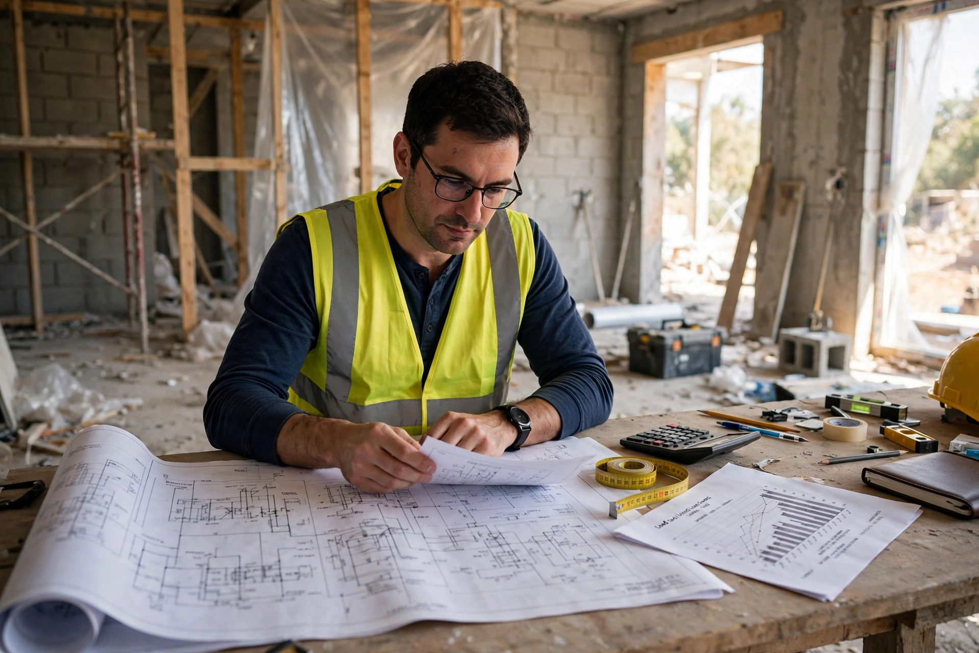
Good electrical work starts with arithmetic, not with a drill. Every appliance the home will run is listed room by room: air conditioners, geysers, ovens, washing machines, water pumps, lighting and socket loads. Each load is converted into amps, a diversity factor is applied, and the total decides the main cable size, the main breaker rating and the sanctioned load. At Goodwell Technical Services, every home electrical installation begins with this written load schedule, because guessing the load is how homes end up with breakers that trip every summer evening.
Circuit planning follows the numbers: heavy appliances each get a dedicated circuit, lighting and sockets sit on separate circuits, kitchens and bathrooms get protected circuits, and spare ways are left for future additions like an extra AC or EV charger. Deciding all of this on paper costs nothing; changing it after plaster costs a finished wall.
- List every load: ACs, geysers, kitchen appliances, pumps, lighting and sockets, room by room, in watts.
- Apply diversity honestly: Not everything runs together, but a summer evening comes close. Plan near the peak.
- Size the main correctly: Main cable, main switch and meter capacity all follow the calculated total load.
- Dedicated circuits for heavy loads: Every AC, geyser and oven gets its own breaker and its own wire gauge.
- Leave spare capacity: Empty ways in the DB and one spare conduit run save future breaking and chasing.
Phase 2: Point Marking and Layout (Before Installation)
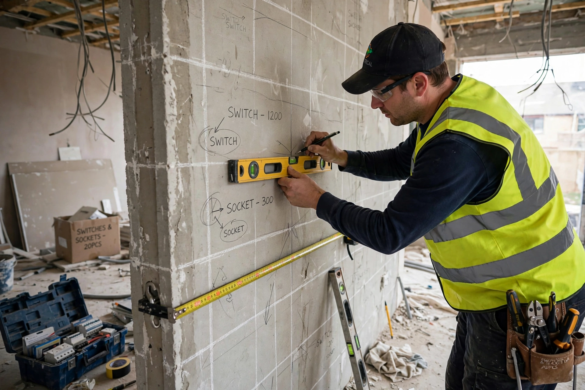
With the circuit plan approved, every point is marked on the bare walls and ceilings before a single channel is cut. Switch heights, socket positions, light, fan and AC points and the DB location are marked with chalk and level, then walked through with the homeowner. This walk-through matters more than it looks: a socket that ends up hidden behind a future sofa, or a switch placed on the wrong side of a door, is a daily irritation for thirty years.
Site discipline matters as much as marking. Our team chalks the furniture layout on the floor so points land where life actually happens, keeps switch plates at one consistent height throughout the house, and plans two-way switching for stairs and long passages. Once approved, every wall is photographed as the working reference for the cutting crew.
- Standard heights, everywhere: Switches at one consistent height, sockets planned around furniture, no random levels.
- Walk it with the homeowner: Every room is checked on foot before cutting; changes are free only at this stage.
- Plan two-way switches: Stairs, corridors and master bedrooms get switching from both ends.
- Mark the DB position early: The distribution board sits accessible, dry and central to keep runs short.
- Photograph every wall: Marked layouts are recorded so nothing is lost once cutting begins.
Phase 3: Conduit and Box Fixing – First Fix (During Installation)
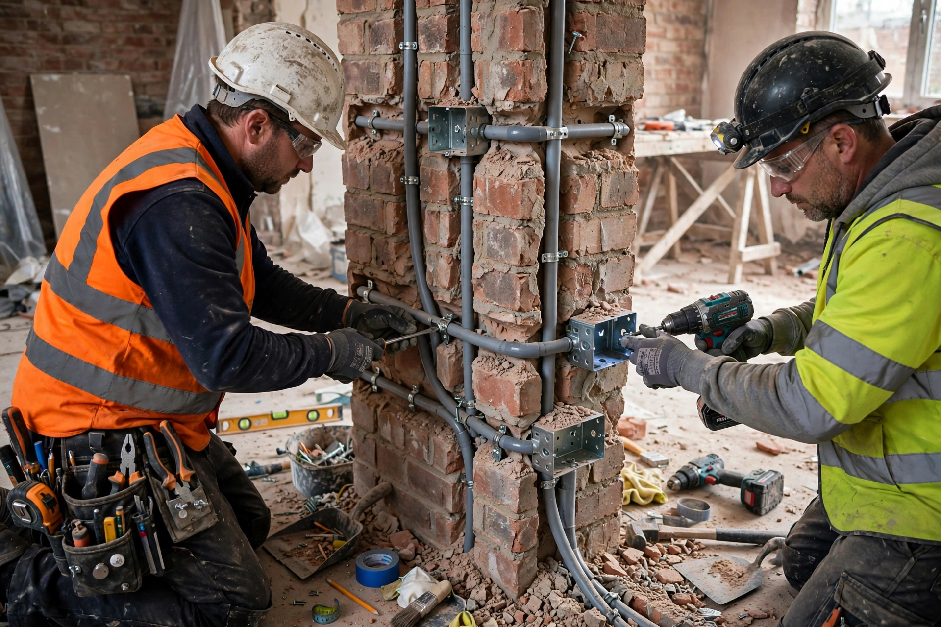
First fix is the skeleton of the installation. Walls are chased with a cutting machine to a controlled depth, ceiling conduits are laid in the slab or fixed to its surface, and conduits run from point to point with boxes at every switch, socket and junction. This is why Goodwell Technical Services fixes conduits with proper saddles and long, gentle bends, because a crushed conduit or sharp elbow can never be rewired again.
Quality here is invisible but permanent. Conduit sizes match the cables they will carry, runs stay strictly vertical and horizontal so future drilling can avoid them, and every box is set to the exact finished wall level, allowing for plaster and tile thickness.
- Chase, do not smash: Machine-cut channels at controlled depth protect wall structure and plaster.
- Gentle bends only: Sharp bends and crushed conduit make future rewiring impossible; use proper bends and couplers.
- Respect the fill ratio: A conduit carries only as many cables as it can hold loosely; overfilled pipes overheat cables.
- Boxes set to finished level: Box edges must finish flush after plaster and tiles, never buried behind them.
- Leave draw wires: Every conduit run gets a draw wire so cable pulling is smooth and insulation is never scraped.
Phase 4: Cable Pulling and Wiring (During Installation)
Once plaster has cured, the cables go in. Single-core copper cables in the standard colour code, brown or red for live, blue or black for neutral and green-yellow for earth, are pulled through the conduits circuit by circuit. Cable gauge is matched strictly to the load it will carry: lighter gauge for lighting circuits, heavier for power sockets, and the heaviest runs for air conditioners, geysers and ovens.
Joints are where wiring jobs live or die. Goodwell Technical Services allows no twisted, taped joints hidden inside conduits or buried where nobody can inspect them; every joint is made in an accessible box with proper connectors, and every cable end is ferruled and tagged so the dressing crew knows exactly which wire is which circuit.
- Copper only, correct gauge: Wire size follows the circuit load; undersized cable is a fire waiting for a hot day.
- Respect the colour code: Live, neutral and earth colours stay consistent in every room.
- No hidden joints: Every joint lives in an accessible box with proper connectors, never taped inside a conduit.
- Label every cable end: Ferrules and tags at both ends make testing, dressing and future repairs fast and safe.
- Protect the insulation: Cables are pulled with draw wires and patience; scraped insulation becomes a future short circuit.

Phase 5: DB Panel Installation and Dressing (During Installation)
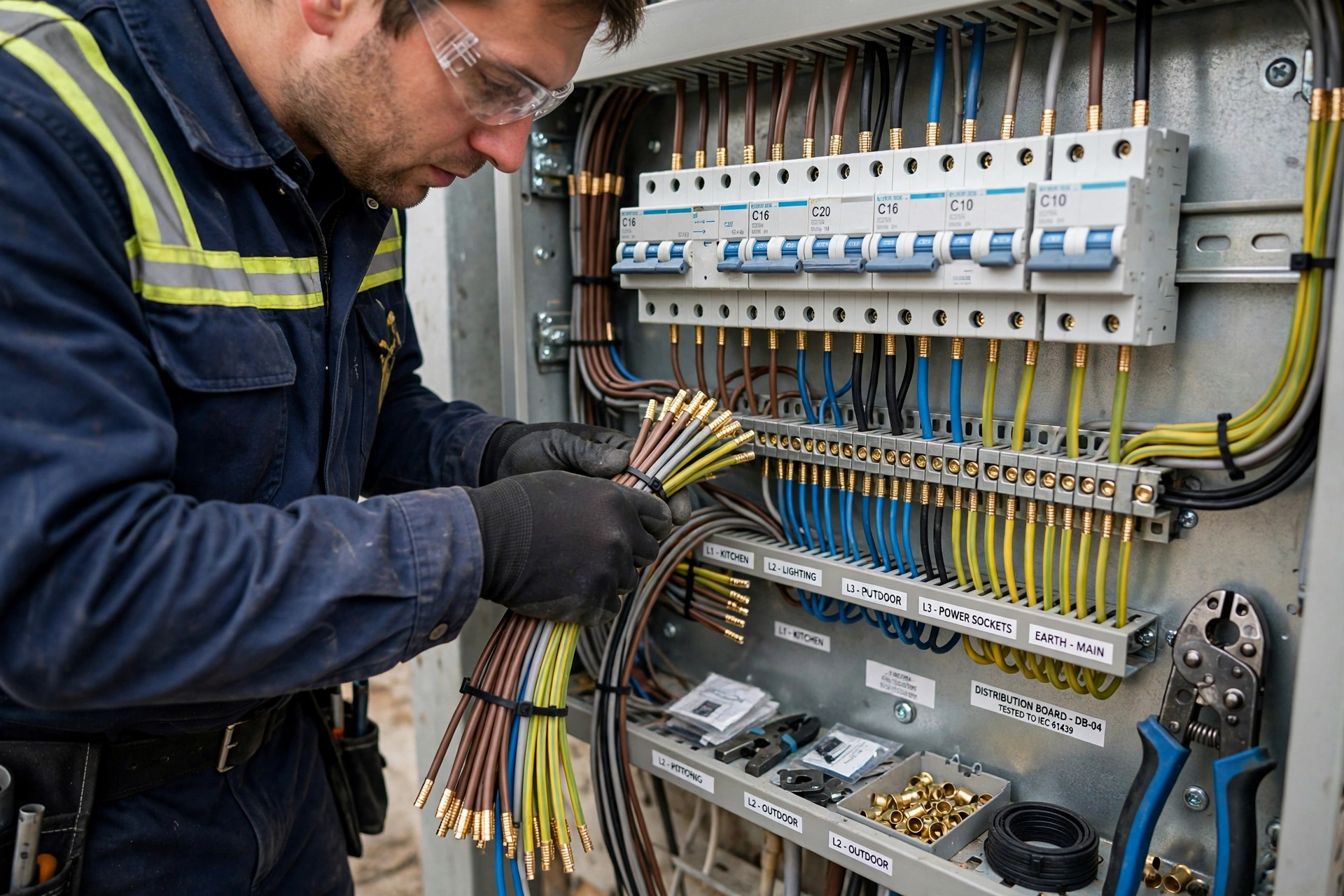
The distribution board is the heart of the home electrical installation, the one place where every circuit can be protected, isolated and controlled. The DB is fixed at the marked position, the main incomer is connected through a main switch with RCCB or RCBO earth leakage protection, and individual MCBs are assigned circuit by circuit exactly as the load schedule planned. Busbar sizing, breaker ratings and cable entries all follow the original calculation, not whatever happens to be in the store.
Dressing is the craft inside the panel: cables are routed in neat looms, bent at clean right angles, terminated with proper lugs and ferrules, and never left as a tangled nest. Goodwell Technical Services never energises a panel that has not been dressed and checked wire by wire, because a tidy DB is not about looks; it is what makes a fault findable in minutes instead of hours, years later.
- RCCB protection first: The whole installation sits behind earth leakage protection that trips before a shock can kill.
- Right breaker for every circuit: MCB ratings match the cable gauge and the load, never one size for all.
- Neat looms, clean bends: Dressed cables with lugs and ferrules; no force, no tangles, no stray copper strands.
- Spare ways stay spare: Planned empty slots stay available for future circuits instead of being filled at random.
- Torque every terminal: Loose terminations heat up under load, so every screw is checked twice before closing.
Phase 6: Earthing System Installation (During Installation)
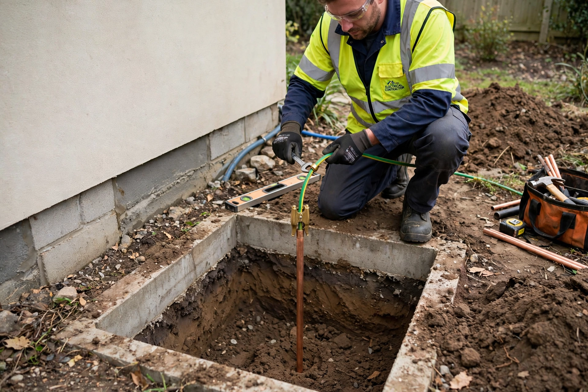
Earthing is the silent safety system that gives fault current somewhere to go that is not through a member of the family. The home electrical installation experts at Goodwell Technical Services install a dedicated earth electrode, a copper plate or rod in a treated earth pit, or a chemical electrode where soil is dry or rocky, bonded to the DB earth bar with a heavy gauge conductor.
Every metal part that could ever become live joins the same system: appliance bodies through the earth pin of every socket, metal conduits and boxes included. Earth resistance is then measured with an earth tester and recorded, because a beautiful earth pit with a high resistance value is decoration, not protection.
- One system, bonded together: DB, sockets, metal parts and pipework all connect to the same earth network.
- Measure the resistance: The earth pit reading is tested and recorded; a low resistance value is the whole point.
- Heavy gauge earth wire: The conductor from pit to DB is sized for full fault current.
- Keep the pit maintainable: The earth pit stays accessible under its cover; periodic watering keeps resistance low.
- Earth every socket: The third pin is genuinely connected in every single socket. No exceptions, no dummy earths.
Phase 7: Switches, Sockets and Light Fittings – Second Fix (During Installation)
Second fix is where the installation becomes visible: switch plates, socket outlets, ceiling roses, fan regulators, dimmers and light fittings are mounted on finished walls and connected to the waiting cable ends. Plates are set level and aligned in clean rows, and every accessory is matched to its duty: heavy sockets where the kettle will live, a heavy duty switch for the geyser, and IP-rated fittings wherever water is nearby.
For fitting styles and lighting ideas, homeowners often browse the Goodwell Technical Services homepage to see how completed rooms balance warm and cool light. Layered lighting, ceiling light, wall lights and task lights on separate switches, is connected exactly as planned, including two-way switching on stairs and passages.
- Level plates, aligned rows: Accessories sit straight and in line; crooked plates betray a rushed job instantly.
- Match the accessory to the load: Heavy appliances get heavy duty switches and sockets, never standard plates.
- IP-rated fittings in wet zones: Bathrooms and outdoor points receive moisture protected accessories only.
- Test each point as fitted: Every switch and socket is proven working the day it is fixed, not left for handover.
- Finish one room at a time: Completed rooms are cleaned and closed, keeping the site orderly.

Phase 8: Testing and Insulation Checks (After Installation)
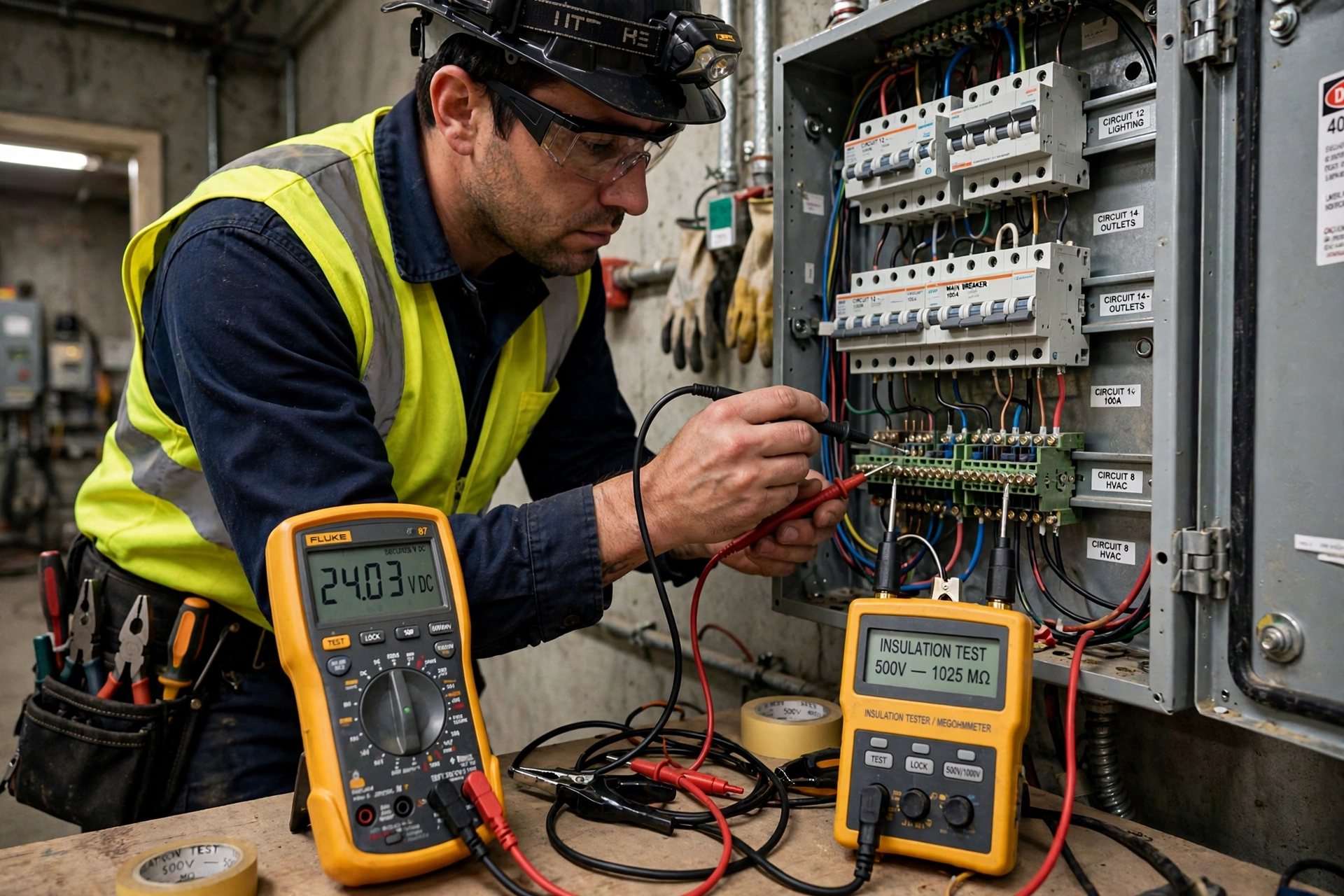
Before any circuit is energised permanently, the entire installation is tested with instruments, not optimism. Goodwell Technical Services runs insulation resistance tests on every circuit with a megger, checks polarity at every socket, verifies earth continuity from the furthest point back to the DB, and proves every RCCB trips within its rated time using a proper tester, not its test button alone.
Every result is recorded on a test sheet, circuit by circuit. A low insulation reading is never argued with; the circuit is opened, the fault is found, whether a plasterer’s screw through a cable or moisture in a junction box, and the test is repeated until the numbers pass. This paperwork becomes the baseline for every future electrician.
- Insulation resistance on every circuit: Megger readings must meet the standard; low readings mean find the fault.
- Polarity and continuity proven: Every socket is checked for correct live, neutral and earth with a socket tester.
- RCCB trip tested: Earth leakage devices are proven to trip at their rated current and time with an instrument.
- Record everything: Test results are recorded circuit by circuit and handed over.
- Never energise a failure: A circuit that fails testing stays off and isolated until it passes. No exceptions.
Phase 9: Load Balancing and Circuit Labelling (After Installation)
In homes with a three-phase supply, daily comfort quietly depends on balance. Goodwell Technical Services measures the running load on each phase with a clamp meter while the house is in normal evening use, then moves circuits between phases until no single phase carries a heavy overload while the others idle. Balanced phases mean no nuisance tripping, no lights dipping when a compressor starts, and a main breaker that works only when it should.
Labelling finishes the panel properly: every MCB gets a clear printed label naming its room and load, and a circuit chart is fixed inside the DB door. Five years from now, when something fails at midnight, that chart is the difference between isolating one circuit in seconds and switching off the whole house in the dark.
- Balance by measurement: Clamp meter readings under real evening load decide the arrangement, not guesswork.
- Spread the heavy loads: ACs, geysers and kitchen circuits are divided evenly across all three phases.
- Printed labels, not pen marks: Every breaker is labelled with its room and appliance in a lasting format.
- Circuit chart in the DB door: A full schedule of circuits, ratings and cable sizes stays with the panel forever.
- Recheck after any change: Any circuit added later triggers a fresh balance check and a chart update.

Phase 10: Final Inspection, Handover and Safety Tips (After Installation)
The final walk-through covers every room with the test sheet in hand: every light is switched on, every socket proven, every fan regulator run up and down, and the DB is opened once more for a visual check of terminations and labels. Goodwell Technical Services closes every snag before handover and leaves the homeowner the test certificates, circuit chart and warranty cards in one folder, because an electrical installation is only finished when it has been proven and documented. To book a site visit for your own electrical project, reach out any time.
Safety then becomes a household habit, and the handover includes the simple rules that keep it that way: test the RCCB monthly, never overload one socket with multi-adaptors, keep water away from outdoor points, and call a qualified electrician rather than opening the DB yourself. Goodwell Technical Services offers periodic electrical health checks for completed projects, retesting insulation and earthing before small faults grow into dangerous ones.
- Prove every point live: Lights, sockets, fans and bells are all demonstrated working at the walk-through.
- Test the RCCB monthly: Press its test button every month; a stuck RCCB is no protection at all.
- Never overload sockets: Multi-adaptors stacked on one point are the most common home electrical fire cause.
- Keep the documents together: Test certificates, circuit chart and warranties in one folder.
- Book an annual health check: Retest earthing and insulation once a year, ideally before the summer load season.

Common Mistakes to Avoid During Home Electrical Installation
Across hundreds of sites, Goodwell Technical Services has seen the same electrical mistakes repeat. Avoid these and your installation will stay safe and trouble free:
- Undersized cables: Saving money on wire gauge buys overheating, voltage drop and fire risk for decades.
- No RCCB protection: An installation without earth leakage protection leaves every possible shock unguarded.
- Hidden taped joints: Joints buried inside conduits cannot be inspected and fail silently inside the walls.
- Overloaded circuits: Too many points on one breaker means constant tripping, or a breaker that never trips when it should.
- Dummy earth connections: Sockets with the earth pin left unconnected look perfectly safe and protect absolutely nothing.
- Mixing wire colours: Ignoring the colour code turns every future repair into a dangerous guessing game.
- Skipping the tests: Energising an untested installation hands all of its hidden faults directly to the family.
Conclusion
Home electrical installation rewards planning and punishes shortcuts. Calculate the load before installation, fix conduits with gentle bends during installation, dress the DB properly, earth the whole system, and finish with instrument testing, load balancing and a documented handover after installation. Follow these ten steps and your home wiring will stay safe, cool and silent for decades.
For wiring done right the first time, contact Goodwell Technical Services for complete home electrical installation, from load calculation and first fix to testing, balancing and final handover, executed step by step exactly as described above.